
Ready boiler house
12 MW hot-water boiler house, turnkey
Packaged modular 12 MW boiler house on natural gas (with liquid-fuel capability) — supply, installation, commissioning and service.
A turnkey 12 MW hot-water boiler house — a complete technological package. Configuration: 3 × FG-W4000 with MB600 monoblock burners, plus automation, water treatment, pipework, power supply and an enclosure building.
Solution configuration
- Thermal output
- 12 MW
- FG-W boilers
- 3 × FG-W4000
- Burners
- MB600
- Water treatment
- 12 m³/h
- Building (approx.)
- 15 × 15 m
COMPLETE HOT-WATER BOILER PLANT
1.1 Hot-water boiler
An automatic hot-water boiler for gaseous and liquid fuels. Three-pass design, with a furnace whose cooled reversing chamber is enclosed in a water-cooled membrane wall, an internal injector to raise the return-water temperature, and two passes of fire tubes arranged in a ring.
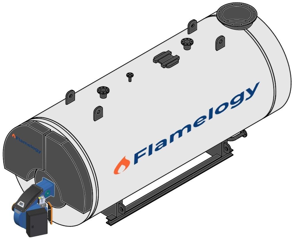
The flame tube forms the combustion chamber with the burner built into the front cover of the boiler at the inlet. Manholes and inspection openings for internal inspection of the boiler are provided in the shell.
Table 1. Main technical data of the boiler
| Parameter | Value |
|---|---|
| Boiler type, 3 pcs. | FG-W4000 |
| Nominal operating gauge pressure | 6.5 bar(g) |
| Max. permissible gauge pressure | 7.5 bar(g) |
| Boiler safety-valve opening pressure | 7.5 bar(g) |
| Max. permissible coolant temperature | 115 °C |
| Boiler thermal efficiency with economiser | 93 % |
| Nominal outlet water temperature, winter mode | 110 °C |
| Nominal return-water temperature, winter mode | 60 °C |
| Nominal outlet water temperature, summer mode | 80 °C |
| Nominal return-water temperature, summer mode | 40 °C |
1.2 Main boiler equipment
| Assembly / section | Name | Quantity | Specification / range |
|---|---|---|---|
| Boiler | Safety valve | 2 pcs. | DN 50/80 PN16 |
| Boiler | Thermometer with pocket (flue-gas outlet) | 1 pc. | 0–350 °C |
| Boiler | Shut-off valve, drain | 1 pc. | DN50 PN16 |
| Hot-water outlet | Emergency thermostat | 1 pc. | 115 °C |
| Hot-water outlet | Boiler flooding sensor | 1 pc. | — |
| Hot-water outlet | Pressure sensor | 1 pc. | 0–16 bar |
| Hot-water outlet | Temperature sensor | 1 pc. | 0–200 °C |
| Hot-water outlet | Pressure gauge | 1 pc. | 0–16 bar |
| Hot-water outlet | Thermometer | 1 pc. | 0–200 °C |
| Hot-water outlet | Wafer check valve | 1 pc. | DN 125 PN16 |
| Hot-water outlet | Wafer butterfly valve with actuator | 1 pc. | DN 125 PN16 |
| Return-water inlet | Pressure sensor | 1 pc. | 0–16 bar |
| Return-water inlet | Temperature sensor | 1 pc. | 0–120 °C |
| Return-water inlet | Pressure gauge | 1 pc. | 0–16 bar |
| Return-water inlet | Thermometer | 1 pc. | 0–120 °C |
| Return-water inlet | Wafer butterfly valve | 1 pc. | DN 125 PN16 |
| Boiler | Boiler expansion tank | 1 pc. | — |
| Return-water preheating to the boiler | Wafer butterfly valve | 1 pc. | DN 65 PN16 |
| Return-water preheating to the boiler | Wafer check valve | 1 pc. | DN 65 PN16 |
| Return-water preheating to the boiler | Control valve | 1 pc. | DN 65 PN16 |
| Return-water preheating to the boiler | Pump, approx. 5 m head | 1 pc. | DN 65 PN16 |
1.3 Monoblock burner
Burners are used across a wide range of industrial and process applications, from energy, heating and waste incineration to chemical, refining and other processes. Automatic monoblock burners with their own fan provide complete combustion of gaseous and liquid fuels for steam, hot-water and hot-water boilers, furnaces, dryers, heaters and steam generators.
SCOPE OF SUPPLY:
The standard delivery of a monoblock burner includes the burner with an integrated fan, an automatic control system, safety devices and gas fittings, including a gas filter, two shut-off valves and a control damper. In addition to the standard delivery, we offer modifications or extensions of the configuration with other accessories and complete equipment.
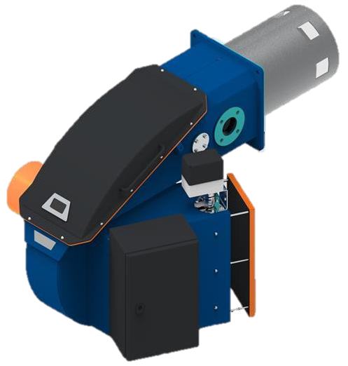
A burner with electronic fuel-air ratio control. The air-fan motor speed is regulated by a frequency converter.
Main technical data:
Scope of supply:
- Automatic monoblock gas burner
- Equipment:
1 pc. natural-gas filter
2 pcs. solenoid valve
2 pcs. gas pressure switch (MIN/MAX)
1.4 Boiler control system
A basic boiler control unit that regulates the burner output according to the set outlet temperature. It controls the boiler pump, monitors the return-water temperature to the boiler and detects boiler and burner faults.
The control cabinet is mounted on the boiler. The delivery includes cable connection to the measuring instruments on the boiler. The control cabinet is fitted as standard with a 7-inch touch panel.
2. BOILER-HOUSE EQUIPMENT
2.1 Master control system
The control cabinet of the boiler-house master control system, intended to manage the operation of the boiler.
Monitoring of alarm conditions in the boiler house, namely monitoring of CH₄ and CO gas leaks with electronic locking of the emergency shut-off valve on the gas inlet to the boiler house, monitoring of flooding and overheating of the boiler house, ventilation, speed control of the main circulation pumps and pressure control in the hot-water supply system to compensate for water losses in the system. The control panel is fitted as standard with a 7-inch touchscreen for convenient operation.
2.2 Booster unit with vertical pumps
Automatic pressure-boosting pump stations are intended to increase pressure when replenishing water in the hot-water supply system.
2.3 Air separators, boiler-house outlet DN200 PN10
For complete air removal from heating systems. Air separators increase comfort and improve efficiency. Removing air from the system water extends the service life of pumps, control devices and other system components.
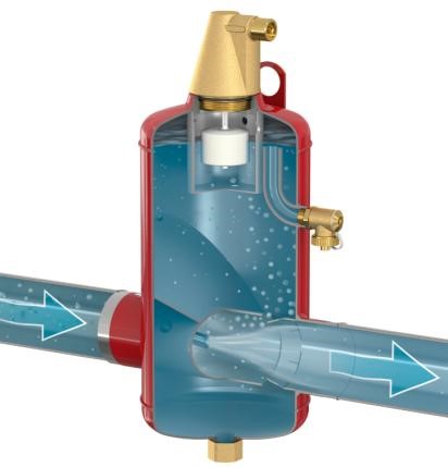
- Flanged connection per EN 1092-1 PN16
- Extremely low hydraulic resistance, reducing energy consumption
- Stable performance throughout the service life
- Low maintenance costs
2.4 Dirt separators, boiler-house inlet DN150 PN16, DN200 PN16
For use in closed heating systems. Dirt separators protect boilers, pumps and fittings from damage caused by the settling of dirt particles. They prevent dirt particles from settling in the boiler. Removing dirt particles from the system water extends the service life of pumps, control devices and other system components.
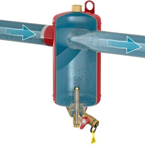
- Flanged connection per EN 1092-1 PN16
- Extremely low hydraulic resistance, reducing energy consumption
- Twenty-five ultra-strong neodymium magnets are built into the separator design
- Stable performance throughout the service life
- Low maintenance costs
2.5 Chemical water-treatment unit, 12 m³/h
Water softeners with two vessels and brine tanks. Both vessels have separate control valves, allowing them to operate at up to double the nominal capacity. The two control valves are connected by a communication cable. They monitor each other's operating status. Only one valve can regenerate at a time, which ensures a continuous supply of softened water.
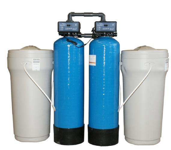
The parallel duplex water softener can be expanded at any time in the future by connecting three or more vessels via the communication cable. This allows the system capacity to be further increased.
Accessories:
- Mechanical pre-filter
- Safety valve
- Vacuum valve
- Chemicals for initial filling – 50 l
- Dosing pump
2.6 Prefabricated piping elements
- Hot-water outlet pipework
- Hot-water inlet pipework
- Natural-gas pipework
- Pipe insulation — sleeve insulation of rock wool with an aluminium-foil surface coating
- Expansion-tank safety valves
- Connecting pipework to the expansion tank
- Flue-gas outlet beyond the boiler house, approx. 5 m + 1 bend
2.7 Boiler-house enclosure, approx. 15 × 15 m
The building is designed with a gable roof supported on a frame structure with solid walls. The roof structure uses the lightweight METSEC truss system. The roofing is made of PUR sandwich panels providing sufficient thermal resistance for the building's energy efficiency. The walls are clad with PIR panels mounted vertically, giving the structure a more aesthetic appearance without the need for metal trims to cover the panel joints.
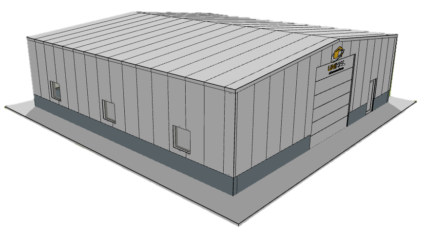
Access to the room is provided by fire doors in a more distinct colour. Natural lighting is provided by several sets of windows located in the upper half of the wall, ensuring even illumination of the whole hall as well as sufficient provision for expansion relief. The expansion-relief windows are designed in accordance with applicable standards. The hall is equipped with electrically driven sectional gates with integrated pass doors. One external wall is designed to be solid, without windows or doors.
2.8 Ventilation
The boiler-house building will be fitted with ventilation louvres to provide natural air exchange inside the boiler house.
To remove heat from the boiler house, fans will be installed that switch on as soon as the temperature in the boiler house reaches the set threshold.
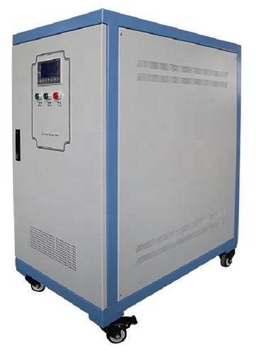
2.10 Three-phase industrial automatic AC voltage stabiliser, 200 kVA
The proposed industrial AC voltage stabiliser is air-cooled, three-phase and four-wire. This series of automatic compensated voltage stabilisers is specially designed for more demanding industrial applications requiring a more reliable and practically maintenance-free solution.
Voltage-stabiliser characteristics:
Smooth automatic voltage regulation
Compliance with international standards
The three-phase industrial automatic AC voltage stabiliser is designed using the latest technologies to maintain a stable output voltage in the event of fluctuations in the external power network and load changes that cause voltage fluctuations.
Options
3.1 Gas generator in a soundproof enclosure
A gas generator in a soundproof enclosure (three-phase 400/230 V 50 Hz), chassis / enclosure F1, with an automatic control panel, engine-driven.
Chassis / enclosure: A soundproof canopy with top air discharge. Crane lifting is by the top lifting eye in the centre or by the metal plates on the sides depending on the model, or by forklift from below. Wide doors and convenient access to all components for maintenance. Doors with stainless-steel hinges and a keyed lock. The canopy is painted with epoxy powder paint, oven-cured, for high corrosion resistance. High-density mineral wool 50 mm thick is used for noise reduction. A residential-grade exhaust silencer is installed inside the canopy.
Standard reference ambient conditions per ISO 8528-1:2005: 1000 mbar, 25 ºC, 30% relative humidity.
Prime Power (PRP): In accordance with ISO 8528-1:2005, prime power is the maximum power that the generator set can continuously deliver while supplying a variable electrical load for an unlimited number of hours per year under agreed operating conditions, provided the maintenance intervals and procedures specified by the manufacturer are followed. The permissible average output power (Ppp) over 24 hours of operation must not exceed 70% of PRP.
Emergency Standby Power (ESP): In accordance with ISO 8528-1:2005, standby emergency power is the maximum power available during a variable electrical load sequence under stated operating conditions, which the generator set can deliver in the event of a mains-power failure or during testing, for up to 200 hours of operation per year, provided the maintenance intervals and procedures specified by the manufacturer are followed. The permissible average output power over 24 hours of operation must not exceed 70% of ESP.
| Parameter | Value |
|---|---|
| Fuel | natural gas |
| ESP | 220 kVA / 176 kW |
| PRP | 200 kVA / 160 kW |
| Voltage | 400/230 V |
| Engine speed | 1,500 rpm |
| Circuit breaker | 4 P |
| Engine governor | electric |
| Cooling | water |
Notes:
The scope of supply includes a cooling-jacket heater with a circulation pump and a battery charger.
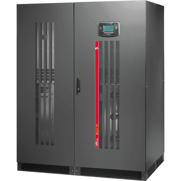
3.2 Uninterruptible power supply (UPS) 200 kW
Zero Impact Source
The UPS offers the additional advantages of the Zero Impact Source concept, implemented through an IGBT-based rectifier unit. This eliminates problems related to installation in limited-capacity networks where the UPS is powered by a generator set, as well as cases of compatibility issues with loads that generate current harmonics. The UPS has virtually no impact on the power source, whether it is the mains or a generator set:
- input-current distortion <3%;
- input power factor 0.99;
- power walk-in function ensuring a gradual start-up of the rectifier;
- start-up delay function for re-enabling the rectifiers after mains power is restored, when several UPS units are in the system.
Battery care system: maximum battery protection
The UPS includes a range of features designed to extend battery life and reduce their usage intensity, including various charging methods, deep-discharge protection, current limiting and voltage compensation according to the battery-room temperature.
Full galvanic isolation
The UPS is equipped with an output isolation transformer (delta zig/zag type) on the inverter as part of the inverter circuit inside the UPS cabinet, providing galvanic isolation between the load and the battery and increasing system-configuration flexibility.
Main features
- high efficiency up to 99.4% (STANDBY ON mode);
- compact dimensions;
- reduced weight for a transformer-based UPS;
- double protection of the load with respect to the battery, both electronic and galvanic.
Not included in supply
- On-site installation
- Chimney
- Other additional equipment
- Connection to heat, water and gas distribution networks
- Extension of the hot-water supply system (heat network outside the boiler house)
- Operation approvals with local authorities
- Commissioning works
- Anything not expressly stated in the specification
Warranty
24 months from commissioning, provided that commissioning and equipment setup are carried out by an authorised service team, but no longer than 30 months from the date of sale.
The exact configuration is defined during the design stage after order confirmation.
Planning an energy project?
Tell us about your task — we’ll propose a solution and prepare an offer.